INSTALLATION INSTRUCTIONS
For Paralan Part Number MH19
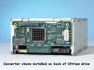
LVD to HVD SCSI Converter
LVD to HVD SCSI Converter
Installation of this Converter on an Hewlett-Packard Ultrium LTO tape drive may require a Torx T10 screw driver. Because the Converter is a bare board, the installation must be performed at an ESD workstation.
The following assumes that a bare tape drive and a Model MH19 Converter in its ESD protective bag are on the workbench in front of the installer. After the experience of installing a few Converters on tape drives it should then take only 60 seconds or so to install a Converter.
Each Model MH19 Converter is shipped with a small bag containing the following installation parts:
- 3 Ea - Square Bumper 10 mm square X 2.5 mm high (0.4 X 0.1 inches)
- 2 Ea - Stainless Round Spacer 6 mm diameter X 6 mm long (0.24 X 0.24 inches)
- 2 Ea - Stainless Screw 3m X 0.5 mm X 12 mm (0.5 inches) long panhead Torx T10 head with crest cup conical washer
- 3 Strips - Velcro with adhesive backing
|
|
Look at the back of the tape drive. If it has two round holes (7 mm diameter - .28 inches) in the back of the case approximately 10 mm (0.4 inch) in from each side and 4 mm (0.15 inch) above the connector cutout, use Procedure A below. If these holes are not on the drive, use Procedure B below. Note: Procedure B may be used to mount the Converter on either version of the HP Ultrium drive, however, if the holes are in your tape drive, Procedure A is preferred as it provides a more secure mounting.
PROCEDURE A
- Break the paper seal and remove the Converter from the ESD bag. Because this is a bare PCB, it is necessary that the installer wear ESD protection.
- Remove the hardware from the small bag. The Velcro strips will not be used in this procedure.
- Remove the paper backing from the adhesive on the back of one of the bumpers. Avoiding contact with the adhesive, place the bumper in one of the three locations on the back of the Converter (the side without the heatsink). Refer to Fig 1. Repeat for the other two bumper locations.
- Place the tape drive face down on the workbench.
- Place the two 6 mm (0.24 inch) long spacers from the hardware bag in the round openings in the back of the tape drive.
- Making sure it is correctly oriented, plug the male connector on the back of the Converter into the female SCSI connector on the tape drive. Push it firmly onto the connector to assure that it is fully seated.
- Place the two 12 mm (0.5 inch) long Torx head screws with washers through the lower holes in the Converter (Fig 1, holes A and B), through the 6 mm (0.24 inch) spacer and screw them into the threaded holes in the frame of the tape drive. Tighten them to 6 in-lbs.
- The SCSI connector on the MH19 Converter provides a HVD SCSI interface. There are no adjustments or settings to be made on the Converter.
|
PROCEDURE B
- Break the paper seal and remove the Converter from the ESD bag. Because this is a bare PCB, it is necessary that the installer wear ESD protection.
- Place the tape drive face down on the workbench.
- For best adhesion of the adhesive-backed Velcro strips, the back of the drive should be free of all oil and other contaminants.
- Take the three strips of Velcro from the small hardware bag. The other hardware in this bag will not be used in this installation
- Remove the paper backing from the adhesive on one side of each of the three Velcro strips. Avoiding contact with the adhesive, place the three Velcro strips on the back of the Converter in the positions shown in Fig 2. Note that there are specific locations for each of the three different sizes of Velcro.
- Remove the paper backing from the other side of the three strips of Velcro installed in step 3. Avoid contact with the adhesive.
- Making sure it is correctly oriented, plug the male connector on the back of the Converter into the female SCSI connector on the tape drive. Push it firmly onto the connector to assure that it is fully seated. Then push on the Converter board in the locations of the adhesive-backed Velcro to assure good adhesion of the Velcro to the back of the tape drive.
- The SCSI connector on the MH19 Converter provides a HVD SCSI interface. There are no adjustments or settings to be made on the Converter
|
Return to MH19 LVD to HVD SCSI Converter page ( http://www.paralan.com/mh19.html )
For technical support, contact Paralan at: scsi@paralan.com FAX: 858-560-8929 or call: 858-560-7266.